Do You Face These Challenges Too?
Weighbridges provide weight only, not volume.
Manual measurement is time-consuming and error-prone.
Loading anomalies (overload, off-center load) are hard to detect quickly.
Load data must be manually entered into management systems.
Separate entry/exit lanes make it difficult to link empty and loaded states.
Application Scenario
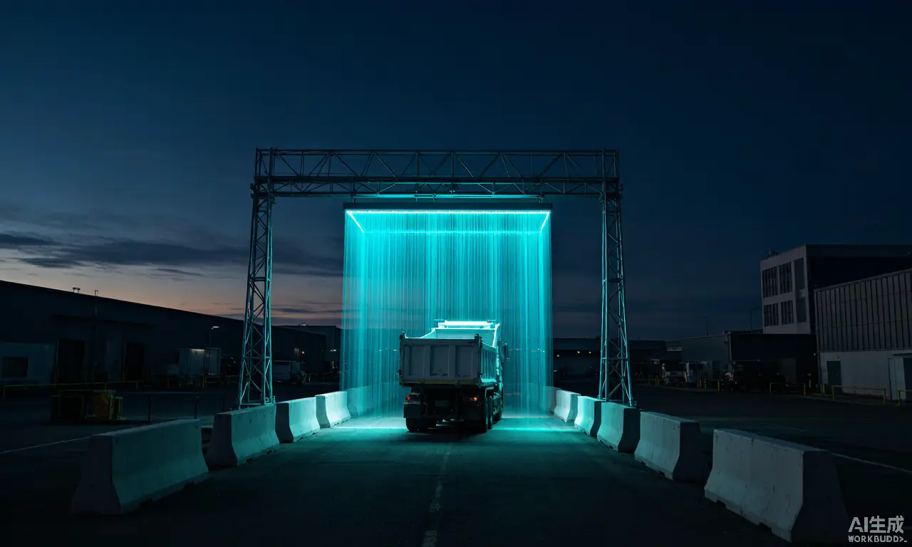
Trucks pass through the measurement lane at a steady speed below 5 km/h. Two LiDAR sensors mounted vertically above the lane automatically scan the truck bed and load, generating 3D point cloud data. Load volume is calculated by comparing empty and loaded states, then recorded and uploaded automatically.
Solution Overview
Two single-line LiDAR sensors are mounted vertically above the measurement lane: LiDAR 1 scans the truck's cross-section profile while LiDAR 2 detects vehicle speed as it passes. Data from both sensors is fused into a 3D point cloud, and Neuvition's proprietary 3D reconstruction algorithm compares the point clouds of empty and loaded states to precisely calculate load volume. With integrated RFID or ANPR automatic vehicle identification, the system supports automatic vehicle data extraction, volume measurement, data recording, and statistics, and integrates seamlessly with PLC control systems and upper-level management platforms.
Solution Highlights
- Dynamic scanning with no stopping required (speed <5 km/h)
- Automatic 3D truck bed dimension recognition
- Multi-lane entry/exit measurement with automatic empty/loaded state correlation
- Bidirectional measurement with automatic vehicle orientation detection
- Automatic recognition of truck bed ribs to avoid volume misjudgment
- Seamless PLC control system integration.
System Components
LiDAR (VI-K30) ×2, edge computer (lw-3610), power cabinet (LCC), RFID or ANPR identification module, license plate camera (optional), LED display (optional), volume measurement software (VI-VMS-D)
Key Parameters
| LiDAR model VI-K30, ToF ranging, measurement range 1–30 m (10% reflectivity) / 1–80 m (90% reflectivity), FOV 270°, angular resolution 0.25°/0.5°, sampling rate 36,000 points/s, frame rate 25/50 Hz, IP65. Dynamic measurement speed <5 km/h; accuracy ±3% (12–25 m³) / ±2% (>25 m³); installation height ≤7.5 m. Operating temperature −25 °C to +50 °C (standard) / −55 °C to +70 °C (wide-temperature VI-K30). Applicable vehicle size: 4000–18000 mm × 2000–3000 mm × 2000–4000 mm. Volume is obtained as the full truck passes through the scanning area. |
Reference Scenarios (Anonymized)
- Coal truck volume measurement: at a coal mine transport site, the system scans loaded trucks on entry and exit, enabling automatic load recording and anomaly review.
- Biomass power plant fuel truck measurement: volume measurement of biomass fuel transport vehicles to support fuel intake management.
- Cement plant clinker truck measurement: deployed at the raw-material transport stage for automatic clinker load statistics.
- Grain sampling inspection truck measurement: in a grain storage inspection scenario, the system assists with grain load volume measurement and data recording.
Competitors / Alternatives
Weighbridge, manual measurement, vision camera solutions, drone surveying, handheld LiDAR surveying
Customer FAQ
Does the vehicle need to stop during measurement?
No — the dynamic solution requires no stopping; the truck simply passes through at a steady speed below 5 km/h.
How is the system installed?
Two LiDAR units and a power cabinet are mounted above the measurement lane; the system is ready after calibration.
Can it integrate with PLC and management systems?
Yes — direct PLC communication via supported protocols, plus an API for upper-level management systems.
Does dust or rain affect measurements?
Light rain or snow is acceptable; heavy dust or water vapor can affect accuracy.
What is the measurement accuracy?
±3% (12–25 m³) and ±2% (>25 m³).
Are there installation height limits?
≤7.5 m is recommended; up to 9 m is possible (accuracy varies with mounting height).
Full workflow from survey to delivery
Site survey
Engineers assess the measurement lane environment and determine the installation plan.
Installation
Two LiDAR (VI-K30) units, power cabinet, and RFID/ANPR identification modules are mounted above the lane.
Calibration
System calibration and empty-state baseline collection, integrated with PLC and the management platform.
Handover & training
System acceptance, then operator and maintenance training.